

ESP32 setup: Install drivers, Arduino IDE, ESP32 board package, connect board, upload Blink sketch.
Most ESP32 boards use either the CP210x or CH340 USB-to-Serial chip.
https://raw.githubusercontent.com/espressif/arduino-esp32/gh-pages/package_esp32_index.json
To identify the correct COM port:
Open File → Examples → 01.Basics → Blink.
Replace the LED pin with the built-in LED pin of your ESP32 (commonly GPIO2):
Click the Upload button.
If the upload does not start automatically, press and hold the BOOT button on the ESP32 until the upload begins, then release it.
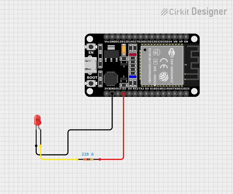
Most ESP32 development boards have a built-in LED connected to GPIO2, so no external connections are required.
| ESP32 | Component |
|---|---|
| GPIO2 | LED Anode (+) through a 220 Ω resistor |
| GND | LED Cathode (–) |
a
void setup() {
  pinMode(2, OUTPUT);
}

void loop() {
  digitalWrite(2, HIGH);
  delay(1000);
  digitalWrite(2, LOW);
  delay(1000);
}